Key words grinding wheel, grinding|2020-10-13 09:48:18|Source 3D printing technology reference
The post-finishing workload of 3D printed metal parts is very low, and grinding has the potential to become an effective solution to meet the final tolerances.
The widespread use of additive manufacturing in the aerospace and medical markets has prompted people to continuously increase the requirements for finishing the surface of additive components to meet the final application needs. The additive manufacturing process can produce components close to the final shape, significantly reducing the need for final finishing. Through additive manufacturing, material waste rate can be reduced, which is beneficial to the overall manufacturing process, but this also means that the subsequent finishing process has more stringent requirements for post-processing technology and consistency. Therefore, it is necessary to ensure the consistency of post-processing and meet the requirements of component tolerance and surface quality. In applications that require higher tolerances and surfaces, grinding can be another effective option for additive manufacturing.

Compared with other traditional material removal processes, the surface quality and integrity obtained by grinding are better. In order to further understand the finishing of additive manufacturing, especially when it is applied to nickel-based superalloy parts in the aerospace industry, engineers from Norton|Saint-Gobain conducted a fine grinding study on Inconel 718 samples manufactured by additive manufacturing. The research mainly revolves around 3 questions: What is the minimum amount/volume of material that needs to be removed from an additively manufactured component? What kind of surface finish can be achieved when grinding additively manufactured parts with the latest generation of grinding wheels? Third, what effect does fine grinding have on the surface residual stress (if any) of the additive manufacturing component?
The AM IN718 samples manufactured using the direct metal laser sintering (DMLS) process were provided by Stratasys Direct Manufacturing. Figure 1 shows the additive manufacturing test sample. After the additive manufacturing, the sample is subjected to media sandblasting to eliminate stress after completion. This is followed by hot isostatic pressing, solution treatment/annealing and precipitation hardening treatment. The sample hardness is 40 HRC. Then use the Norton NQX60E24VTX2 grinding wheel on the Magerle MFP-125.50.65 intermittent feed grinding machine of Norton|Saint-Gobain Higgins Grinding Technology Center for sample grinding. Figures 2 and 3 show the test setup.

Figure 1 AM Inconel 718 test sample before grinding

Figure 2 Machine settings

Figure 3 Device close-up
First, gradually increase the depth of cut, grind several areas, determine the minimum amount of material that needs to be removed, and process the surface of the additive manufacturing. After grinding according to the specified cutting depth, the surface is checked for obvious defects. Figure 4 shows the sample pictures after the parts are cleaned during the experiment. According to the experimental results, in order to eliminate all geometric inconsistencies and surface defects generated in the additive manufacturing process, approximately 0.30 to 0.45 mm of material needs to be removed from the component.
The grinding length used in this test is 50.8mm, the diameter of the grinding wheel is 462mm, and the working speed is 23m/s. A total of five material removal rates (MRR) were tested, ranging from 0.1mm3/sec./mm to 3.9mm3/sec./mm. Adjust the material removal rate by improving the feed speed (mm/min) or cutting depth (mm). A number of material removal rates were tested to evaluate the effect of medium and low material removal rates on surface finish and grinding ability. Although it is possible to use modern engineering abrasives to grind nickel-based alloys (such as Inconel 718) with a higher removal rate, according to the current industry standard finishing rate for finishing standard Inconel workpieces, this study chose a lower Material removal rate (Figure 4). Taking standard (non-additive manufacturing) workpiece grinding as an example, the expected result is that as the material removal rate increases and the grinding power increases, the surface finish (Ra) of the ground workpiece will increase or the surface will become rougher .

Figure 4 AM Inconel 718 test sample after partial grinding
Before and after grinding, the Federal Contact Profiler System 5000 is used to measure the surface finish of the workpiece. The measurement points include multiple positions and two directions on the workpiece (Figure 5a and Figure 5b). In addition, non-contact profilometer surface measurements were performed at multiple locations.

Figure 5 (a) Surface roughness measurement direction (parallel to the grinding direction); Figure 5 (b) Surface roughness measurement direction (perpendicular to the grinding direction)
Before grinding, after evaluating the surface finish of the additive manufacturing material, it was found that the finish was very different in different measurement directions. When measured longitudinally, the average finish was 3.3μRa; when measured horizontally, the average finish was 2.1μmRa. When measuring the standard as-cast Inconel 718 material, this significant difference does not appear. This difference seems to be related to the 3D manufacturing method, but the exact reason is still unclear.
The conventional method of measuring the surface finish after grinding with a contact profiler is perpendicular to the grinding line instead of parallel to the grinding line. In this study, the surface finish was measured in two directions parallel to the grinding line and perpendicular to the grinding line. Then compare the measurement results after grinding with the longitudinal and transverse measurement results before grinding.
The important point is that when measuring the ground surface along the direction perpendicular to the grinding line, the stylus will cross the crests and troughs of the grinding line. When measuring in a parallel direction, the stylus moves parallel to the grinding line and never crosses the peaks and valleys. Therefore, as expected, in this study, the (rough) surface finish obtained by vertical measurement was significantly higher than that obtained by parallel measurement.
After evaluating the surface finish of the additive manufacturing material before and after grinding, it was found that there were significant differences in the finish in different measurement directions. In this study, two directions parallel to the grinding line and perpendicular to the grinding line were used to measure the surface finish, and the results did have significant differences. When measured in a parallel direction, the average surface finish is 3.3μmRa before grinding and 0.21μma after grinding. When measured in the vertical direction, the average surface finish is 2.1μmRa before grinding and 0.5μmRa after grinding.
In addition, Nanovea 3D surface profiler and white light chromatic aberration technology were used to analyze the additive samples, and the surface features were visualized. In this test, after receiving the additive manufacturing sample, the glass medium was used for media sandblasting to remove the convex part of the surface. The lines that can be seen on the surface after grinding are the lines left by the grinding operation. Grinding wheels with finer abrasive grains or other polishing products, such as engineering abrasive belts, can be used to further reduce surface lines and form super fine surfaces, provided that this is critical to the performance and quality of the components.
In order to further understand the impact of grinding on the overall surface integrity of AM IN718 samples, Bruker-AXS D8 Discover micro-diffraction equipment was used. After the samples were received and ground, the surface residual stress was measured. After comparing the measurement results of 6 different positions of the same sample under the two conditions, it is found that the residual stress near the surface under the two conditions is negative/compressive. This situation mainly occurs on the components after fine grinding. The residual stress near the surface is compressible, which can delay the spread of surface cracks and improve the fatigue life.
During this study, the grinding power was measured according to 5 material removal rates. As the material removal rate increases, the grinding power also increases. This behavior is present in most grinding operations. At the lowest speed of 0.1mm3/sec./mm, the peak power during grinding is 1.4 kW. At the highest material removal rate of 3.9 mm3/sec./mm, the grinding power is 10.8 kW.
The results of this study prove that the fine grinding of additively manufactured nickel-based alloys (such as Inconel 718) can reduce the surface roughness by nearly 94% (parallel to the grinding line) or 34% (perpendicular to the grinding line) ). You can use grinding wheels with finer abrasive grain size or other grinding products, such as engineering abrasive belts, to obtain ultra-fine surfaces according to requirements. In addition, the results also show that in order to improve the surface fineness, 0.30 to 0.45 mm of material needs to be removed from the components and all geometric inconsistencies related to the 3D manufacturing process are removed. For additive manufacturers, the lowest removal rate is the key message, as they have been striving to achieve the most cost-effective way to achieve near-net shape for additive manufacturing components. In addition, the residual stress data shows that the surface stress after grinding is compressible, which can delay the expansion of surface cracks, thereby prolonging the fatigue life of the manufactured components.

-All diamond tools can be ordered and fabricated!
- Henry Wang | Quote Manager
-WhatsApp:+86-13459035657
-Email: ceo@zdiamondtools.com
-Web www.zdiamondtools.com
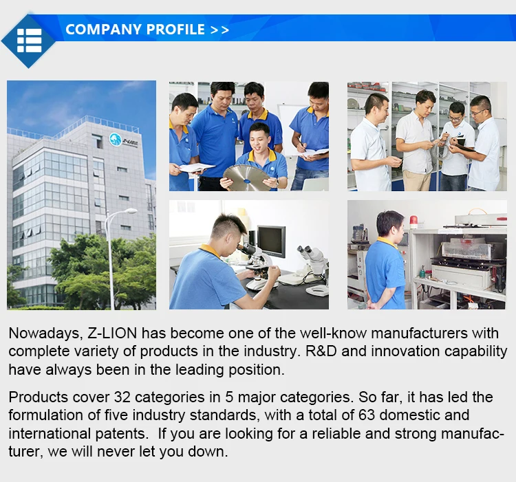
Company Profile
Certifications
Company Team

Exhibition
Logistics

FAQ